Overview
The operator of a large natural gas storage facility determined that a vertical liquid separator vessel rated for 4,000 psig MAWP and minimum design metal temperature (MDMT) of ─20 F (─29 C) had experienced service temperatures as low as ─43 F (─42 C) during withdrawal operations. The operator needed to understand the risk of brittle fracture, as well as the potential need for nondestructive examination.
The Challenge
The operator required a detailed and sophisticated assessment of the vessel’s fitness for service, risk of brittle fracture, possible nondestructive examination plan, and safe working envelope of pressure versus temperature with a 2-week turnaround time.
RSI’s Solution
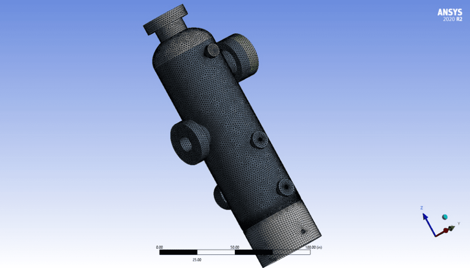
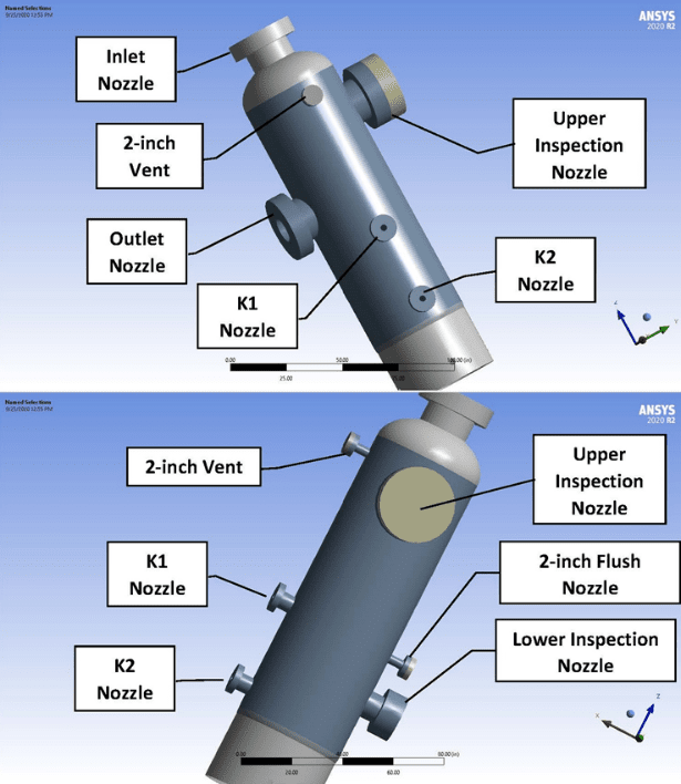
RSI immediately commenced a review of the vessel design and fabrication package including component MTRs and welding inspections, analysis of the operating and environmental conditions, analysis of nozzle loadings from the attached piping, and development of a 3-D FEA model of the vessel.
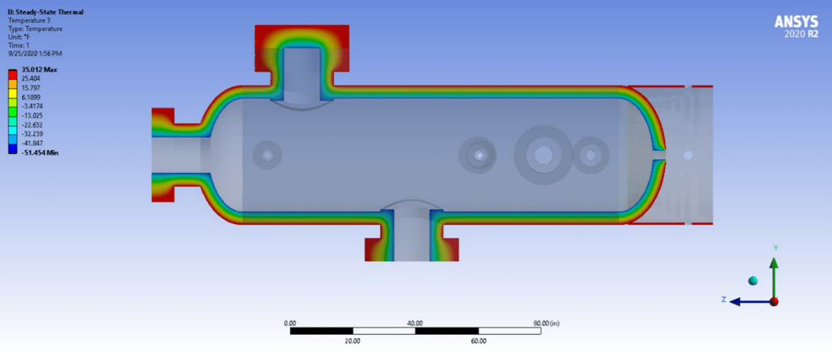
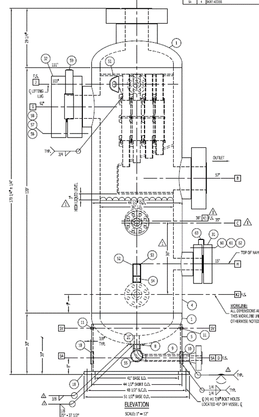
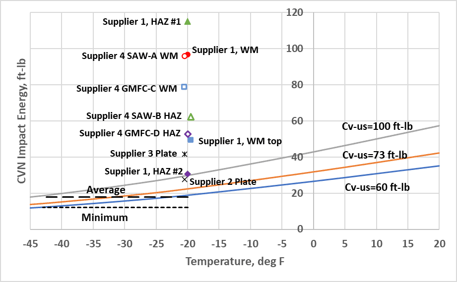
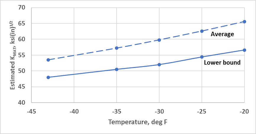
The vessel shell had a 10-ft height,3-ft inner diameter, and 4.25-inch wall thickness, using components manufactured and sourced globally. Charpy V-notch (CVN) test had been performed on the shell and head plate stock with simulated heat treatment, and on the combination-process welds, at the MDMT. RSI estimated the expected CVN upper shelf impact values and the CVN brittle-ductile transition curve over the range of temperatures from ─45 F to +20 F at the mean and upper and lower bound levels. The CVN tests performed at the MDMT were generally well above the curves suggesting actual transition temperatures were lower. The CVN values projected to ─45 F suggest that at that temperature the vessel code average and minimum impact values would have been met or exceeded. The projected CVN values were used to estimate fracture toughness, KMAT, in accordance with API 579, Section 9F.
The vessel was evaluated for stresses due to self-weight, internal pressure, piping nozzle loads, and through-wall differential temperature considering the full range of seasonal temperature conditions. The FEA mesh was appropriately refined at the nozzle joints.
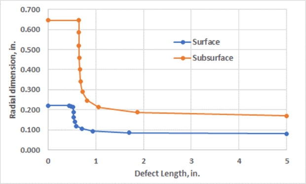
The vessel construction documents confirmed that the welds were 100% examined by RT and UT techniques and were repaired as necessary to meet the criteria of the edition of ASME BPV Section VIII at the time of construction. However, the NDE reports did not describe the locations and dimensions of acceptable imperfections that were left in place. The Code flaw acceptance criteria were reviewed to determine the ranges of maximum dimensions of surface flaws or embedded flaws that could have remained in each weld in the vessel.
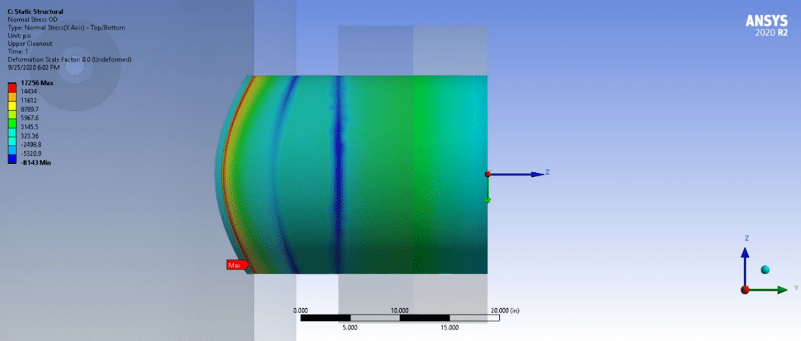
The detailed FEA stress results, the potential welding flaws, and the projected KMAT values were applied as inputs to Failure Assessment Diagram (FAD) Level 2 analyses set forth in API 579. A FAD analysis was performed for each nozzle weld and shell weld, for the maximum-acceptable size surface or embedded flaw in orientations appropriate to the weld orientation. The assessment accounted for the through-thickness variations of stress using fourth-order polynomial interpolations.
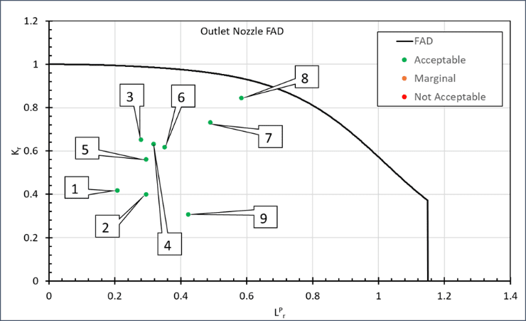
The analysis determined that operation of the vessel outside the rated design temperature conditions did not put the vessel in danger of brittle fracture. Consideration for the number of excursion events suggested that enlargement of the acceptable initial welding imperfections by fatigue was highly unlikely. Therefore, a reinspection was deemed to be unnecessary. The results were also used to project a fracture-safe operating pressure-temperature envelope to assure continued safe operation. Where specific nozzles were limiting, the operator could opt to inspect the governing nozzle(s) to confirm an absence of the limiting flaw configurations.