Overview
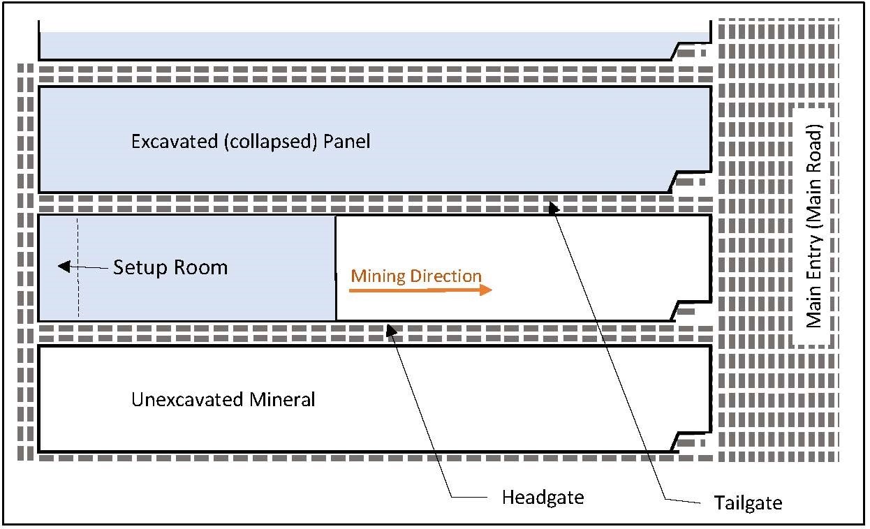
Longwall mining is a highly efficient method of mineral extraction, which removes a high percentage of a mineral seam. Modern longwall mining is almost fully automated. A typical longwall panel is between 600 and 1,500 ft wide and up to several miles long. Before a panel is developed, gateroads are mined along the sides of a panel (in the panel longitudinal direction) to provide access to the back of the panel. The gateways are supported on unexcavated pillars, and typically consist of 2 to 3 entries with one or two rows of columns (chain pillars). Once access to the back edge of the panel is provided a chamber is mined along the back edge (set-up room) and a shearer is situated in the chamber. The shearer works from back towards the main entry.
This gateway is used for the transportation of mineral, equipment, and personnel and is known as the headgate. The gateway that is adjacent to a previously extracted panel is subject to lateral pressure due to the collapse of the previous panel. This gateway, known as the tailgate, is used for ventilation and as an emergency escapeway. The total extraction of mineral within each panel and subsequent collapse of the ceiling causes significant settlement and horizontal displacement at the ground surface. The maximum subsidence at the ground surface can vary from 25% to 95% of the height of the excavated volume depending on the depth and stiffness of the subsurface strata.
Case Study
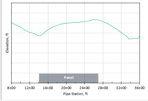
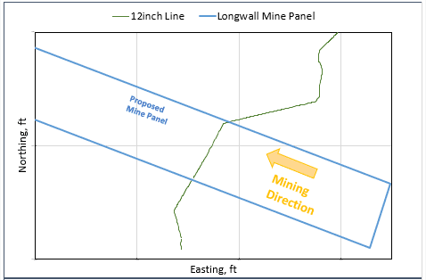
In this case study a natural gas pipeline was expected to be affected by ground subsidence from a longwall panel in Appalachian regions. The proposed panel was approximately 1200 ft side. The pipeline was approximately straight in plan view with a near normal angle to the panel, however, the elevation profile along the interface was hilly.
RSI Solution
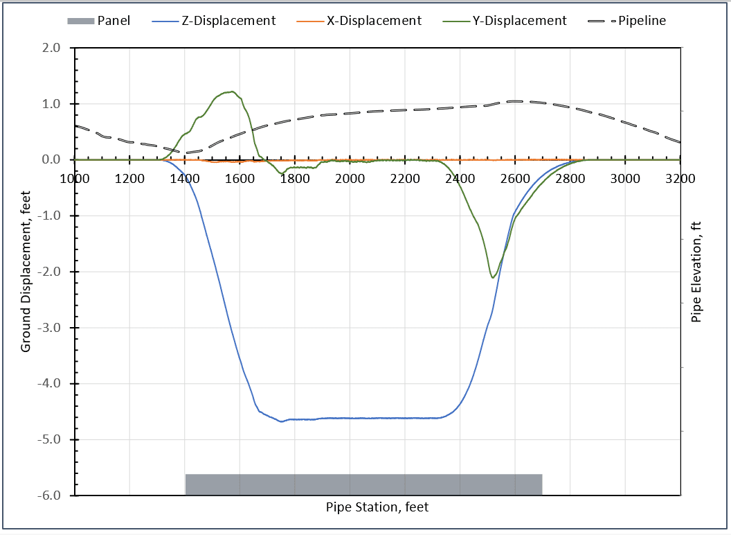
RSI performed a soil-pipe interaction analysis to calculate the stresses in the pipeline. Since data was not available on the amount of expected vertical and horizontal subsidence displacements the ground displacements would have to be predicted. RSI employed the influence function method (Luo and Peng 1989; Peng 2006) to calculate the expected displacements, accounting for the effect of ground slope using a model developed by Luo and Peng (1999) for hilly terrains.
In a pipe soil interaction analysis, soil springs are defined to represent the stiffness of soil surrounding the pipeline, while the pipeline is modeled using pipe elements. Pipe elements account for the effect of the internal pressure on pipe curvatures (Bourdon’s effect).
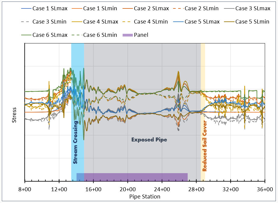
RSI performed the analysis for various loading scenarios including ground displacements, the maximum and minimum pipe internal pressures, and the maximum and minimum expected differential temperatures. The ground displacements were also calculated for several intermediate locations to resemble the progress of the panel front. The analysis showed that if the pipeline remained buried during the subsidence both the stresses would exceed the allowable limits. RSI recommended that the pipeline be exposed. Analysis of the pipe under exposed conditions used soil-pipe contact elements along the proposed exposed locations to represent the friction between the pipe and the soil. The analysis showed that the pipeline would have to be exposed along the majority of the panel and to some distance (~200 ft on the north) out from the north edge of the panel.
An additional analysis was conducted to determine if several soil plugs could be left unexcavated along the pipeline. In particular, exposing the pipeline along a stream crossing would pose several challenges, including concerns regarding the stability of the ditch. The analysis results showed that a soil plug could be left unexcavated at the stream crossing. It was also shown that a portion of the pipeline outside of the panel near the northern edges could remain buried provided that the cover depth would be reduced to 2.5 ft.